Schematics
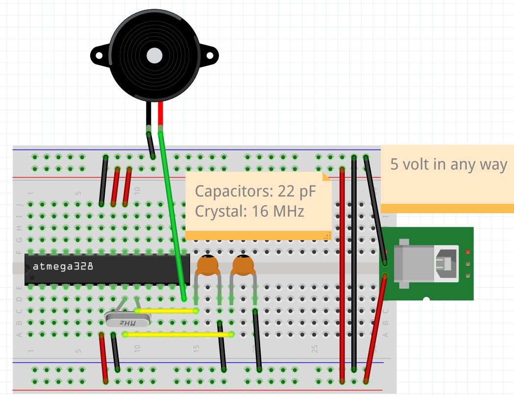
Build the schematic as such, using the chip with The Minimal Pi Clock program on it.
In which orientation must I have the chip?
The notch of the chip must be at the left:
The notch of the chip must be at the left.
Can you show the wiring of the chip as a table?
Yes.
Here is an equivalent table:
| Pin | 1 | 2 | 3 | 4 | 5 | 6 | 7 | 8 | 9 | 10 | 11 | 12 | 13 | 14 |
|---|---|---|---|---|---|---|---|---|---|---|---|---|---|---|
| Upper | . | . | . | . | . | . | GND | 5V | 5V | . | . | . | . | . |
| Lower | . | . | . | . | . | . | 5V | GND | X1 | X2 | . | . | . | P |
GND: to ground5V: to 5 voltX1: to a capacitor and crystalX2: to (another) capacitor and (the same) crystalP: to plus of piezo
What does '5 Volts in any way' mean?
Where the schematic states '5 Volts in any way', this means any reasonable way to provide 5 volts for the machine.
In this example, a USB-B female is shown, but any USB connector can be used.
Can I use other electric potenials than 5V?
Yes.
The range of the chip is wider than 5 volts.
Upon powering this, the buzzer will go off for a little more than three seconds.